
Summary
Pressure vessels and storage tanks can over pressure resulting in loss of containment and can be lethal hazards. Pressure relief devices are often used as an effective safeguard against overpressure of equipment. Low pressure relief devices are called as pressure vacuum relief valve (PVRV) or conservation vents. This white paper uses them interchangeably and are to be construed as relief devices that protect low pressure storage tanks that are built to API 620 [1] and API 650[2] code of construction. An important terminology is overpressure percentage and expressed mathematically below,
Overpressure % = (Relieving Pressure – Set Pressure) / Set Pressure * 100
Determination of PVRV capacity must be in consultation with OEM or with OEM software. In addition, it also summarizes methods to determine capacity for any manufacturer and model if data is available. At low overpressure, the PVRV opens and flutters as the stagnation pressure is not sufficient to keep the valve in the open condition. As the overpressure increases the pallet remains open and a sustained flow is achieved. Most manufacturer can sustain flow between 10% to 50% overpressure for PVRV.
Opening characteristics of PVRV
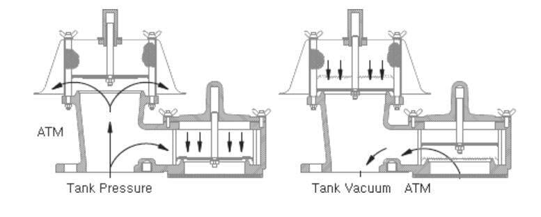
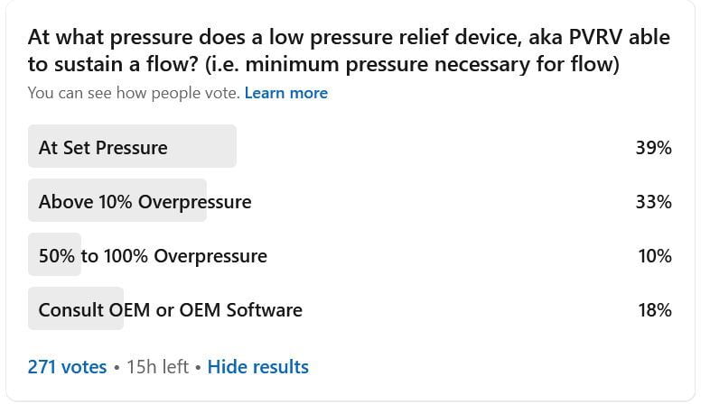
A relief device opens when the upward force exerted due to the system pressure exceeds the downward force exerted due to the weight of the pallet or due to spring constant if a spring is used in lieu of weighted pallets. Springs are used in low pressure relief devices when the set pressure exceeds approximately 1 psig (70 mbarg). All relief devices that protect pressure vessels and storage tanks require overpressure for achieving full lift. A few exceptions are pilot operated pressure relief devices which have the capability to achieve full lift at set pressure. In general, PVRV capacity increases proportional to the lift and reaches an asymptote when it reaches full lift. The low-pressure relief device capacity increases after full lift due to increase in system pressure as the flow is subsonic. The device capacity reported by the manufacturer is often not at the set pressure, rather at an overpressure beyond the set pressure of the relief device. Due to this opening characteristic of the low-pressure relief device, clause 3.6.2.2 from API 2000 [3], seventh edition, specifies that the user ensures that the set pressure be lower than the design pressure of the tank to ensure adequate capacity in excess of the required flow for each identified overpressure scenario. The same is applicable for set vacuum and has to be set higher than the design vacuum of the storage tank. Designers must be cautious and set the pressure/vacuum setting lower than the design pressure and design vacuum of the storage tanks designed to API 650 [2] code of construction as they have 0% accumulation. In summary, stable operation of a PVRV is achieved when there is sufficient pressure differential between the inlet pressure at the nozzle of the PVRV and the back pressure across the device.
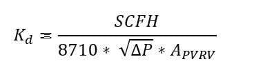
Kaypear conducted a poll on LinkedIn to see if there was awareness of the workings of these low-pressure relief devices. The question asked was, “At what pressure does a low-pressure relief device, aka PVRV able to sustain flow? (i.e. minimum pressure necessary for flow”. 39% of 271 votes chose that the minimum pressure to sustain flow is set pressure. 33% cast a vote of 10% overpressure necessary to sustain a flow through the relief device. The comments indicated capabilities from OEM or from relief valves which have the capability to lift at 10% overpressure. However, PVRVs require anywhere from 10% to 100% overpressure (i.e. 1.1 to 2 times the set pressure) to achieve full lift and dependent on the manufacturer, make and model. Therefore, it is imperative to consult with the manufacturer on the capabilities of the relief device, specifically the minimum required overpressure to sustain flow. In summary, the user must consult with the OEM to ensure that the PVRV has capability to relieve the desired required flow prior to the relieving pressure and only about 18% of the respondents in LinkedIn identified the answer correctly.
Relief Device Capacity Certification as per API 2000
Relief Device Capacity certification as per clause 5.3 of API 2000, seventh edition using two methods, (1) Flow-curve method and (2) Coefficient of discharge method. Both the methods require the manufacturer to test devices with a combination of pipe size configuration, orifice size, and at different pressure/vacuum settings. The devices are to be tested at the minimum pressure / vacuum and the maximum pressure / vacuum setting. Since these extrapolations are to be verified, it is imperative that the manufacture be consulted for the capacity of the relief device. Most major commercially available PVRV manufacturers have proprietary software which is accessible and is shown below alphabetically. Using vendor software to determine the capacity of the PVRV is the best practice.
Original Equipment Manufacturer | Software | Link to access software Software provides easy to use flow vs pressure graphs. Plus a data sheet is also available. |
Groth Corporation | Groth Sizing Program | http://166.78.101.111/Default.aspx |
Protectoseal | PRO-FLOW | https://proflow.protectoseal.com |
Protego | QUick Engineering and Sizing Tool (QUEST) | https://quest.protego.com/login |
Shand and Jurs | Winsize | https://www.ljtechnologies.com/request-winsize/ |
Varec | PRV2Size | https://valvesizing.emerson.com/Software/PRV2SIZEoverview.aspx |
NOTE: Flame arresters can reduce the capacity of the PVRV
Flame arresters are often combined with PVRVs as a means to protect storage tanks from internal deflagrations and to reduce the likelihood of flame propagation back in to the tank. It is important to consider the reduction of capacity of PVRVs due to the installation of a flame arrester. The manufacturer has to be consulted to determine the capacity of a PVRV with an integrated flame arrester design. OEM flow curves or OEM software can provide the capacity when a PVRV is used in combination with a flame arrester.
Capacity Determination for all PVRV for preliminary sizing
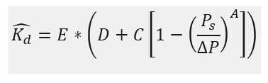
Vendor software provide ready solution and capacity for PVRV. The DiERS method [4] or the Fisher-Forrest [5] methodology can be incorporated to obtain the capacities of PVRV. The DiERS method is published below and is limited to the specific PVRV (model, size, and set pressure). If users have devices in the same size with similar set pressure, then the model is powerful to determine capacities of all PVRV. The coefficient of discharge is first generated for each overpressure increment. The pressure increments can be 1.1, 1.2, 1.5, 1.75, and 2 times the set pressure. For each overpressure increment, the coefficient of discharge can be computed using the following equation:
All units are expressed in US Customary Unts
SCFH, standard cubic feet per hour (measured at 60 °F and at one atm)
∆P, Differential pressure across relief device
APVRV, If nozzle area is not available, then use pipe inside area
The following proposed equations was develop
Where,
Ps, is set pressure of PVRV
∆P, pressure differential between inlet pressure of relief device and back pressure
A,C,D, and E are regression parameters till both Kd are the same
Sum of least squares and other regression techniques can be used for development of these parameters. The user can multiple the theoretical flow with regressed coefficient of discharge expressed as to obtain the device capacity. Fitting parameters can be developed for the make, model, and set pressure for each manufacturer. This can be used for preliminary sizing estimates and the user can confirm the final sizing using OEM curves or OEM software.
References
1 | American Petroleum Instiute, Design and Construction of Large, Welded, Low-Pressure Storage Tanks, API Publishing Services, Addendum2012. |
2 | American Petroleum Institute, Welded Tanks for Oil Storage, API Publishing Services, March 2013. |
3 | American Petroleum Institute, Venting Atmospheric and Low-pressure Storage Tanks, API Publishing Services, March 2014. |
4 | Center for Chemical Process Safety, Guidelines for Pressure Relief and Effluent Handling, Hoboken NJ: John Wiley and Sons, 2017. |
5 | H. Fisher and H. Forrest, "Protection of Storage Tanks from Two-Phase Flow due to Fire Exposure," Process Safety Progress, vol. 14, no. 3, pp. 183-199, 1995. |